Verilog-A
This is a very short introduction to the Verilog-A language
Introduction
Verilog-A is an industry standard modeling language for analog circuits. It is the continuous-time subset of Verilog-AMS , behavioral language for analog and mixed-signal systems derived from the IEEE 1364 Verilog hardware description language (HDL) specification.

Verilog-A language:
is designed to allow modeling of systems that process continuous-time signals.
is multidisciplinary, models for electrical, mechanical, fluid and thermodynamic systems.
supports top-down design and speeds up system simulation times.
Conservative systems
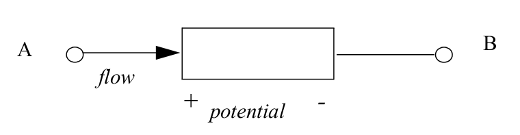
There are two values associated with every node:
the potential (also known as the across value or voltage in electrical systems): the potential of the node is shared with all ports and nets connected to the node.
the flow (the through value or current in electrical systems): the flow from all ports and nets at a node sum to zero.
A branch is a path of flow between two nodes through a component. Every branch has an associated potential (the potential difference between the two nodes) and flow.
A behavioral description of a conservative component is constructed as a collection of interconnected branches satisfying the generalized Kirchoff’s Potential Law (KPL) and Kirchoff’s Flow Law (KFL):
KPL: The algebraic sum of all the branch potentials around a loop at any instant is zero (0).
KFL: The algebraic sum of all flows out of a node at any instant is zero (0).
Natures, disciplines
Verilog-A allows definition of nets based on disciplines. The disciplines associate potential and flow natures for conservative systems (or only potential nature for signal-flow systems).
The natures are a collection of attributes, including user-defined attributes, which describes the units (meter, gram, newton, etc.), absolute tolerance for convergence, and the names of potential and flow access functions.
// Electrical discipline
discipline electrical
    potential    Voltage; // Voltage nature, access function V()
    flow         Current; // Current nature, access function I()
enddiscipline
Signal-flow systems
A discipline may specify two nature bindings, potential and flow, or it may specify only a single binding, potential. A discipline with only a potential nature is known as a signal flow discipline. Module outputs are functions of potentials at the inputs without taking flow into account.
Comments
Note
Reference documentation for Verilog-A can be found in Verilog-AMS reference manual from Accellera:
VAMS-LRM-2-3-1, Annex C
Note
Code highlight in this document is for Verilog HDL specification. Verilog-A reserved words are not highlighted
see VAMS-LRM-2-3-1, Annex B for the list of keywords
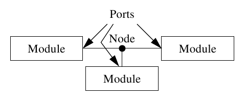
Module, Ports, Hierarchy
The components (modules) connect to nodes through ports to build hierarchy. The description of a system contains instances of modules and how they are interconnected.
Descriptions of primitive modules are given behaviorally. That is, a mathematical description is given that relates the signals at the ports of the module.
Module
The fundamental structural unit within Verilog-A is the module.
A Verilog-A module contains some combination of:
Ports that interface to the external world
Internal nodes local to the module
Parameter and variable declarations
Analog block that specify the module’s behavior
analog statement
only this block can contribute to an analog net
Hierarchical structure (instantiate instances of other modules)
module resistor(p,n);
    inout p,n;
    electrical p,n;
    parameter real r=0 from [0:inf);

    analog      // analog block
        V(p,n) <+ r*I(p,n);

endmodule
Ports
Ports provide a way to connect modules to other modules and devices
A port has a direction: input, output, or inout, which must be declared
The ports are listed after the module declaration
The port type and port direction must then be declared in the body of the module
module resistor(p,n);           module modName(outPort, inPort);
   inout p,n;                       output outPort;
   electrical p,n;                  input inPort;
   ...                              electrical outPort, inPort;
                                    ...
Hierarchy
Modules may hierarchically instantiate instances of other modules or circuit elements:
module rc_filter(in,out);
    inout in,out;
    electrical in,out,gnd;
    ground gnd;

    resistor #(.r(10k)) r1 (in,out);
    capacitor #(.c(10n)) c1 (out,gnd);
endmodule
Data Types
Parameters
real, integer, string
array of the above
Variables
real, integer, string
array of the above
Nets
Branches
Genvars
parameter integer bits = 8 from [1:inf);
inout [1:bits] out; //Vector port (bus) specification
electrical [1:bits] out;
electrical int_node; //Internal node
branch(in, int_node) int_br; //Branch declaration
parameter real thresh = 1.5;
parameter real high = 2*thresh;
real x, y;
real arr[1:bits];
string bit_string;
genvar i; // index for loop that contain a analog operator (transition())
analog begin
    ...
    for (i = 0; i < 8; i = i + 1)
        V(out[i]) <+ transition(value[i], td, tr);
end
Note
See the Data types section in VAMS-LRM-2-3-1
Verilog-A Statements
Variable assignments
Contribution statements 1
Conditional statements
if, then, else
Looping constructs
for, while, repeat
Input/Output Statements 2
textual display ($strobe, $debug, …)
file handling ($fopen, $fstrobe, …)
- 1
See the Analog behavior section in VAMS-LRM-2-3-1
- 2
See the System tasks and functions section in VAMS-LRM-2-3-1
Contribution statements
The branch contribution statement is used in the analog block to describe continuous-time behavior between a module’s analog nets and ports.
for example, electrical behavior can be described using the branch contribution operator <+:
V(n1, n2) <+ expression;
or
I(n1, n2) <+ expression;
Analog Operators
A Verilog-A lauguage defines analog operators for:
Transition operator (transition)
Time derivative and integral (ddt, idt)
Time delay operator (delay)
Laplace transform operator for CT filter (laplace)
Z-transform operator for DT filter (zi)
For example, the transition operator smooths out piecewise constant waveform by defining delay (td) rise time (rise_time) and fall time (fall_time) to signal transitions:
transition ( expr [ , td [ , rise_time [ , fall_time [ , time_tol ] ] ] ] )
...
integer result[0:bits-1];
genvar i;
...
analog begin
    ...
    for (i = 0; i < bits; i = i + 1)
        V(out[i]) <+ transition(result[i], dly, ttime);
end
...
Note
See the Expressions section in VAMS-LRM-2-3-1
Event Driven Modeling
Event-driven modeling uses the @ operator to execute a block of code when an event occurs.
Types of events supported by Verilog-A modeling:
Global events generated by the simulator at various stages of the simulation
@(initial_step()) : At beginning of simulation
@(final_step()) : At end of simulation
Monitored events triggered by change in signals, simulation time, or other runtime conditions.
@(timer()) : Periodically at a specific time
@(cross()) : At analog signal crossings
Event or operator
analog begin
    @(initial_step or cross(V(smpl)-2.5,+1))
    V(out) <+ 0 ;
end
Note
See the Analog behavior section in VAMS-LRM-2-3-1