Design environment
In this project we will use the Virtuoso Platform from Cadence, one of the world’s leading suppliers in electronic design automation. This tool is targeted to design full-custom integrated circuits. This include schematic entry, circuit simulation, full custom layout, physical verification (DRC,LVS) and parasitic extraction.
The technology kit, a 45nm Generic Process Design Kit (GPDK045) is also provided by Cadence Design Systems. This kit include among other:
Spectre Models for simulation
Fixed Layouts & Parameterized Cells
Technology file (where we define the technology rules)
Design Rule Check (DRC: design rules for verification)
Layout Versus Schematic (LVS: rules for comparaison between schematic and mask)
Extraction files (parasitic extraction for simulation purpose)
Design project
Before launching Virtuoso, you need to create a directory for the design project. Open a terminal window and create your own design directory:
mkdir ~/<circuit_design_projet>
cd ~/<circuit_design_project>
This directory must be configured for the Process Design Kit. For that purpose, download the script gpdkinit.py in this directory and execute it:
python gpdkinit.py
You are now ready to launch Virtuoso.
Virtuoso
To run the Virtuoso environment, enter the command /comelec/softs/bin/virtuoso & in the terminal window.
This open the main window of the software known as Command Interpreter Window (CIW).
This window contains the dialog message: messages associated to command are shown in the central area. A command line below allows the user to enter commands to be interpreted in Skill language. The texts at the bottom line indicates the commands associated with the mouse buttons. The top part of the window contains a set of drop-down menus. We will note CIW the start from this menu.
Library Manager
From the CIW, open the Library Manager (CIW -> Tools -> Library Manager)
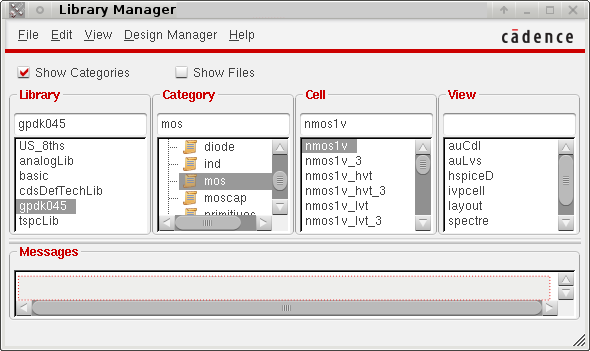
- From the Library Manager window you can access the cells contained in the generic libraries, in the design kit libraries and finaly in your own library:
The column Library contains the names of the available libraries.
The column Cell contains the names of the cells in the selected library.
The column View contains the name of the representation of the selected cell (schematic, layout, …).
An optional Categories column groups the cells in a library in order to make easier cell research. (Select the Show Category button in order to access to the categories)
The top part of the window contains a set of drop-down menus.
We will note LM the start from this menu.
Analysis of a standard-cell
Before designing your own cell, we will analyze a particular D flip-flop of the library.
Library |
Category |
Cell |
View |
gsclib045 |
DFF |
DFFQX1 |
schematic |
and using the right button Open with -> Application :Schematics XL
From the menu of the schematic window choose Launch -> Layout XL and click OK, or answer YES to all questions… (as you can not open the layout view in writing mode, select read mode)
From the menu of the layout window select View -> Zoom to Fit All (or press f key)
Try to recognize the correspondence between the elements of the layout and those of the schematic. (You can select pin in layout (small square filled with blue) and press q key to show the connectivity)
What kind of logic is used in the cell ?
Find the clock input and the Q output.
Note the size (width) of transistors used in the invertors for the clock signal and for the output Q. You will use the same sizes for our future TSPCFF cell.