Documents
Documents are all provided in pdf format.Lectures
- I. Introduction (2 slides per page)
- Video on the introduction to modeling
- What is the interest of modeling?
- What is meant by "abstraction"?
- Video on the introduction to OMG, UML and SysML, second part of the slides
- Find from the OMG website what are the latest (non beta) releases of UML and SysML
- II. Modeling in SysML (2 slides per page)
- Video on Case study
- Install TTool, as explained in the labs
- Start TTool, then open the "File" menu, select "Open project from TTool repository". Then, find the Pressure Controller model and select it. (you need an internet connection for this).
- After the model has been downloaded, you should see all the diagrams of the Pressure Controller system. Browse the different diagrams either with the tree on the left, or with the top tabs. Diagrams wil be progressively explained in the slides and videos. How to use TTool will also be progressively explained.
- Video on Method
- Find out who invented the V-cycle. Where and when was it invented?
- Video on Requirements
- Read the definition on requirements. This definition should give another point of view with regards to my lecture.
- Find the definition of the three relations (composition/containment, refine, deriveReqt), and read them. They shall be a bit different, more generic, because I have defined these relations in the context of embedded systems (so I have made them more explicit).
- List the other relations between requirements I have not presented.
- Video on Partitioning
- Video on Use Case Diagrams
- Find the latest SysML specification in the OMG website. Download this specification. Two Use Case Diagrams are given in Figures D5 and D6 of the SysML standard. What do you think of these diagrams?
- Video on Activity Diagrams
- Video on Sequence Diagrams
- Video on Design (part #1)
- Slide 57: What happens when executing this system? To find the answer, you may think about the depicted system, or you can also go to the section below called "Practising with Block Diagrams": watch the video on TTool, and make the model in the slides within TTool, then simulate it as explained in the video.
(Solution) Actually, nothing happens! Indeed, at first, Block0 tries to send sig1, which is a synchronous signal. Therefore, Block0 must wait for a block to be ready to receive sig1. But block1 is not ready to receive sig1 since it is waiting for sig2. So, there is a deadlock in this system.
- Slide 58: What happens when executing this system?
(Solution) At first, since Block1 waits for sig2 that was not yet sent, Block1 is blocked. Block0 first sends sig1(5), then sig1(6). Since the FIFO is of size 1 with a bucket approach, sig(6) is trashed since the FIFO for sig1 signals already contains sig1(5). Then, sig2(7) is sent, and Block0 terminates. Block1 can now read sig2(7) (so it stores 7 in its x attribute). Then Block1 reads sig1(5) and terminates. The FIFO of sig1 and sig2 are both empty at the end of system execution.
- Slide 59: What happens when executing this system?
(Solution) Block1 cannot execute because it waits for sig2. So Block0 executes first. It sends sig1(5) which is added to the FIFO of sig1. Then, Block0 tries to send sig1(6) but since the FIFO for signals sig1 is full, Block0 cannot perform the sending: Block0 is suspended. Since no block can execute, the system terminates.
- Slide 60: What happens when executing this system?
(Solution) The sending of go_out synchronizes with the receiving of go_in, either in T1 or T2. So, there are two possible executions. (1) Synchronization between T0 and T1 go_out / go_in, then synchronization between done_out(1) and done_in(1), termination. (2) Synchronization between T0 and T2 go_out / go_in, then synchronization between done_out(2) and done_in(2), termination.
- Video on Design (part #2)
- Slide 61: What happens when executing this system?
(Solution) Since the channel is a broacast channel, there are now three possibilities: either T0 and T1 synchonize, or T0 and T2, or T0, T1 and T2. The first two cases are similar to the ones described in previous slide. The last case is as follows. T0 sends go_out and T0 and T1 both receive go_in. Then, there are two subcases. Either T1 exchanges done_out(1) / done_in(1) with T0, and then T2 exchanges done_out(2) / done_in(2) with T0, or either T2 exchanges done_out(2) / done_in(2) with T0, and then T1 exchanges done_out(1) / done_in(1) with T0.
- III. Validation (2 slides per page)
- Video on Verification
- What is the main difference between simulation and formal verification?
- Can you cite and explain the three ways to express properties?
You can try to open this model in TTool as follows:
Find the latest SysML specification in the OMG website. Download this specification.
Exercises
Eurecom 2025 Exercise: Software of a Smart Greenhouse Automation System
System specification
Requirement diagram

(Click to enlarge)
Use Case Diagram

Activity Diagram

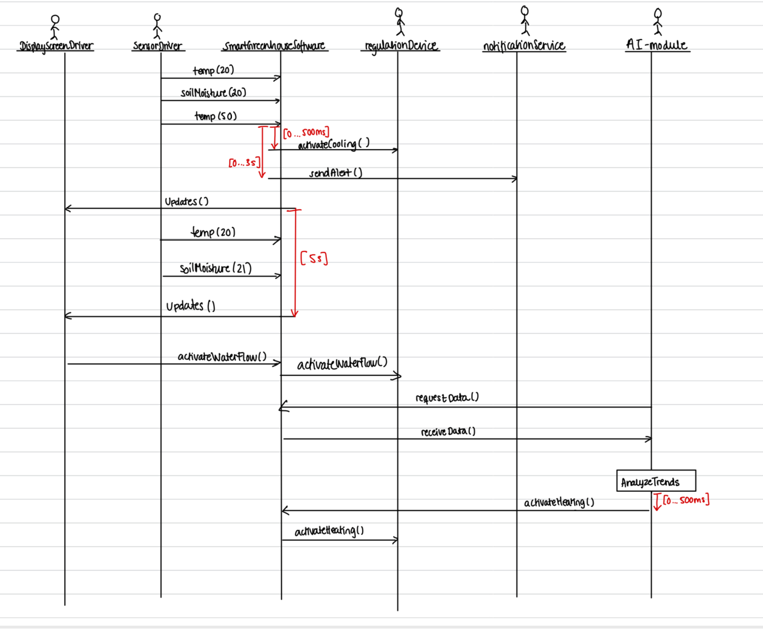
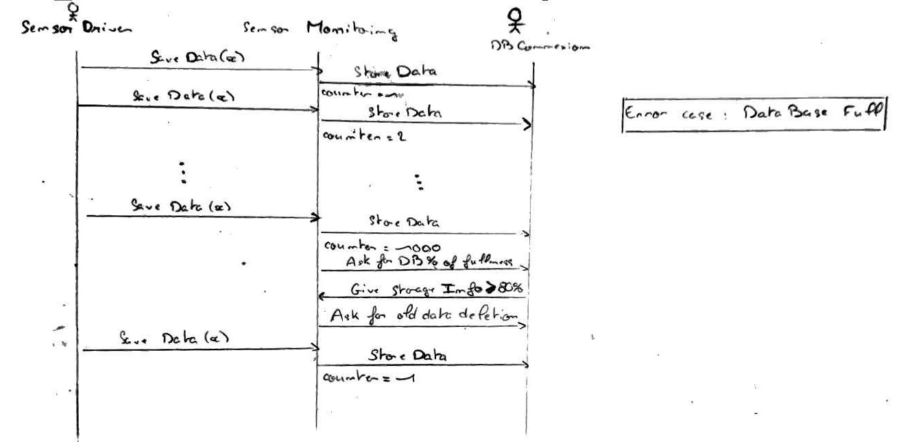
Sequence Diagrams
- Nominal scenario
- Error scenario
Polytech Nice 2023 Exercise: Smoked Salmon Factory
Requirement diagram
Requirements Diagram
Use case diagram
Use Case Diagram